Category: HTF
Heat Transfer Fluid Tech Tips
Cost Effective Alternatives to Changing Thermal System Fluid
By Michael R. Damiani, Radco Industries Inc.
During normal operation, heat transfer fluids can degrade due to thermal stress or oxidation. Fluids can also become contaminated through heat exchanger leaks. Often, degradation and contamination lead to a significant decrease in heat transfer fluid efficiency, increasing production time and costs. In many cases a full fluid change-out may be required to restore system performance, but many times these other cost-effective alternatives listed below can extend fluid life and maximize system performance:
Fluid Reprocessing. Degraded or contaminated fluid is removed from the system and sent to the fluid manufacturer for reprocessing. Low boilers and high boilers are separated by distillation and the recovered heat transfer fluid is sent back to the original user. Reprocessed fluid will usually meet new fluid specifications. Partial fluid volumes can be drained from the system and sent in for reprocessing, allowing continuous operation and eliminating a system shut-down. Reprocessing costs are based on the total quantity shipped and offer significant savings over the purchase of a new charge.
Fluid Filtration. The formation of hard carbon or coke particles can lead to the fouling of heat transfer surfaces. By using portable filtration units brought on site, a service team from a fluid manufacturer can remove these particles either while the system is in operation or during a shut-down. On-site filtration saves transportation costs and fluid drainage time and expense.
Partial Fluid Change-Out. Replacement of a percentage of the initial fluid charge with new fluid can improve performance by diluting degradation by-products and/or contaminates to within acceptable limits. Often the off-spec fluid that was removed from the system can be returned to the fluid manufacturer for credit, or can be reprocessed, returned, and kept on-site for future make-up requirements.
These options can save system downtime and reduce overall heat transfer fluid costs, while maximizing system performance.
How To Extend Heat Transfer Fluid Life
By: Michael R. Damiani
Chief Executive Officer
Radco Industries, LLC
By Utilizing Your Fluid Manufacture’s Product Support Services, You Can Extend the Time Between Fluid Replacements, Lower Your Fluid Make-Up Costs, And Improve System Performance
High temperature heat transfer fluid manufacturers design fluids to operate within the recommended temperature range safely and efficiently for many years with minimal required maintenance. Occasionally, a system upset will occur, drastically affecting the fluid’s heat transfer efficiency and/or thermal stability. System upsets can be caused by a wide assortment of maladies, including heat exchanger leaks, sudden temperature excursions, failed circulation pumps, the addition of a mislabeled drum of fluid to the system, etc. More commonly, over a period of time many heat transfer systems slowly lose their ability to efficiently transfer heat due the fluid’s gradual thermal and oxidative degradation. This usually leads to gradually increasing production times that even the most astute process engineer can miss. In either case, utilizing your heat transfer fluid supplier’s product support services can solve a system problem cost effectively and quickly, and more often than not, without having to drain the system and replace the whole fluid charge. Taking full advantage of a good product support program can save unit downtime, lower fluid make-up rates, and improve overall system performance. Many of these services are on a “no-cost” basis or are relatively cost-effective as compared to the cost of replacing the fluid charge and/or new fluid make-up. Whether it is the case of a sudden system upset or the realization that the system has lost heat transfer fluid efficiency over time, the first phone call made should be to the fluid manufacturer to discuss the situation and review options. Most major fluid manufacturers offer a wide assortment of fluid support programs to aid in maximizing the fluid user’s investment. These programs usually fall under two categories- preventative maintenance services and fluid performance improvement services.Preventative Maintenance Services- The First Step In Extending Fluid Life
Fluid Analysis: Consistent fluid analysis is by far the most important service that should be utilized by every heat transfer fluid user. This service is especially important for newly commissioned systems so that the fluid baseline analysis be established for future comparisons. Consistently taking a periodic representative system sample for analysis is invaluable in many ways- it allows both the user and the fluid manufacturer to track, or “trend” the fluid’s degradation rate (the molecular breakdown due to thermal stress) over time. Evaluating this data can give an accurate prediction of when any action, such as fluid reprocessing or replacement, is required to maintain heat transfer efficiency. An accurate forecast from sample analysis data allows more than adequate time to plan for any needed heat transfer fluid work to be completed during a scheduled shutdown or turnaround, and not on an unexpected or emergency basis. Periodically sampling the system also detects any mechanical problems such as product contamination through leaking or ruptured heat exchanger interfaces. In almost every case, the product that leaks into the heat transfer fluid is not as thermally stable or is as heat transfer efficient. Not only will this lower overall heat transfer system efficiency, in many cases the contaminant can increase the degradation rate of the heat transfer fluid. Sample analysis can catch even minute process leaks into the heat transfer system. Early detection and remedy of a process leak or other outside contamination can save major system problems and heat transfer fluid replacement costs down the road. Most fluid manufacturers recommend that a system sample be analyzed every 6 months. Sample analysis is usually on a “no-charge” basis and many fluid manufactures will supply a sampling kit with written instructions for taking a representative sample, packaging the sample, and returning the kit to the lab. A written report and recommendation is then sent to the user with the results within a week of the lab receiving the sample. Generally, the tests performed include high/low boilers (by both gas chromatography and atmospheric boiling tests), density, moisture, acidity, residual carbon (insolubles), and fire properties (flash point, fire point, and auto-ignition temperature). Correctly interpreted, the data generated from these tests are extremely accurate in revealing overall fluid condition and level of heat transfer efficiency. Technical/Engineering Support: In general, major fluid manufactures’ technical support teams consist of graduate engineers that not only specialize in heat transfer fluids and heat transfer theory, but most aspects of heat transfer system components, design, and system troubleshooting. Many solutions to questions and problems that seem unique and perplexing to a specific heat transfer fluid user can be readily answered with one quick phone call to the fluid manufacturer, or a plant visit by a heat transfer fluid specialist. Advice regarding component specifications- such as fluid compatibilities, pump sizing, expansion tank sizing, seals/gaskets, and instrumentation- for specific applications, temperature ranges, and heat transfer fluids can be also quickly answered. Many heat transfer fluid manufactures also list and recommend quality suppliers of heat transfer system components, which can greatly assist in the design and equipment specification stage of a new project. Finally, most fluid manufactures’ technical support people have years of experience in solving heat transfer fluid-related problems ranging from inherent system/equipment design flaws to accelerated fluid degradation and outside contamination. These technical support teams have the experience to quickly identify the problem and recommend a solution that will correct the situation while minimizing system downtime and heat transfer fluid costs.Fluid Improvement Services- When Something Goes Wrong Or The Fluid Needs to Be Replaced
Replacement/Reprocessing Programs: Most fluid manufacturers recommend fluid replacement when the aggregate high/low boiler (or contamination) level reaches an upper limit of 15%. Even at 10% level, a significant drop in system heat transfer efficiency occurs. If the system charge needs to be replaced either due to catastrophic system upset or from years of degradation or oxidation, a number of options are available from fluid suppliers to minimize downtime. A very common program is the “Fluid Credit Program” where the user drains the existing charge of fluid and returns it to the fluid manufacturer. The recoverable yield is determined (generally no more than 80% is given, even if the yield is higher) and the value of the yield (less a reprocessing charge) is applied against the purchase price of the new fluid cost. This type of program allows for very quick turnaround times. In just about every case, the new charge of fluid can be on-site even before the old fluid is drained from the system. This type of program is especially useful when the scheduled shutdown window is small or the change-out needs to be done on an emergency basis. Generally, a “toll reprocessing” program is much more cost effective for system change-outs as compared to a fluid credit program. Since most high temperature heat transfer fluids have a limited number of components and a defined boiling range, manufacturers with toll reprocessing services can use fractional distillation techniques to easily separate and remove contaminants and high/low boiling degradation by-products from the heat transfer fluid product. Reprocessed fluid many times meets new fluid specifications. With this type of program, the off-spec fluid is removed from the system and returned to the fluid manufacturer for toll reprocessing. The fluid is reprocessed and the user than receives back the actual recovered yield of heat transfer fluid (in many cases the actual yield returned is greater than the maximum 80% allowed in the typical credit program). Both types of replacement/reprocessing programs offer significant new fluid cost savings versus disposal and purchase of a completely new charge. Additional cost savings can be achieved by returning small drum quantities of material generated by leaking pumps, equipment swap outs, system vents, etc. for either credit or reprocessing. Filtration Programs: Filtration is a cost-effective method of removing carbon (coke) and metallic particles suspended in the heat transfer fluid without draining the system and sending the fluid off-site. While permanent filters rated for high temperature duty are recommended for most heat transfer fluid systems, some fluid suppliers offer on-site filtration services with portable high temperature units. In many cases these portable units are able to filter out the carbon and particulates while the system is still in operation, eliminating system downtime. Like all companies that use and depend on high temperature heat transfer fluids, fluid manufacturers are acutely aware of the importance of heat transfer fluids in production units (and also their relatively high cost). Service programs are offered by the manufacturers so that the user can maximize both the performance properties of the fluid and the return on the initial fluid investment. If not already familiar with the fluid support programs and services, the fluid user should ask their fluid supplier for a detailed explanation of all their programs. Chances are, one call to the fluid supplier will lead to extended fluid life and improved system performance.Slipstream Thermal Design
SLIPSTREAM FILTER RECOMMENDATION FOR HEAT TRANSFER FLUID SYSTEM
By: Gerard Bernaldo, BSME Fluid Specialist Engineer & Michael Damiani, Product Manager – MIL Spec FluidsHTF System Filter Recommendation
For most heat transfer fluid systems, Radco recommends a slipstream filter configuration. Compared to a direct “in-line” filter system, a slipstream unit does not require complete system shutdown and cooling for general maintenance. Since most heat transfer systems do not have a filter system installed during initial construction, residual inorganics may be present and/or high levels of carbon (or “coke”) may have accumulated over time. The initial start up of the filter unit will require continuous monitoring and frequent changing of filter cartridges/bags, making the “in-line” filter system impractical. The slipstream filter design offers an inexpensive and a maintenance- friendly alternative to scheduled fluid replacement or reprocessing. The installation of a slipstream filter unit for preventative maintenance will also save system wear and tear on system components and greatly extend the operating life of the heat transfer fluid. Particulates in heat transfer fluids are caused either by polymerization of degradation/oxidation by-products, or are introduced during system construction and consist of inorganic material such as pipe slag, grit, sand, etc.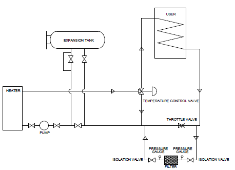 All heat transfer fluids degrade over time due to thermal stress. These degradation by-products, referred to by most fluid manufacturers as “high boilers” and “low boilers”, are molecular fragments formed when the heat transfer fluid’s molecular bonds are broken. These fragments can polymerize with other fragments, creating extremely large molecules which in turn lead to the formation of high molecular weight carbon particulates. These particulates are commonly referred to “coke” or “sludge”.
High and low boilers, carbon particulates, and inorganics have very little of the heat transfer efficiency of the original heat transfer fluid. The presence of high levels of carbonized and inorganic material can cause mechanical problems in the system such as seal and gasket leakage and/or failure, heater tube fouling (decreasing the amount of BTUs transferred to the fluid), and increased pressure drop (due to coking on pipe surfaces). Carbonization in the fluid also specifically affects the fluid’s heat transfer properties such as viscosity and density, lowering the heat transfer coefficient. Therefore, the elimination and/or reduction of carbon and organics in the heat transfer fluid will lead to longer periods of time between fluid change-outs, higher fluid efficiency, and decreased downtime required for system maintenance.
All heat transfer fluids degrade over time due to thermal stress. These degradation by-products, referred to by most fluid manufacturers as “high boilers” and “low boilers”, are molecular fragments formed when the heat transfer fluid’s molecular bonds are broken. These fragments can polymerize with other fragments, creating extremely large molecules which in turn lead to the formation of high molecular weight carbon particulates. These particulates are commonly referred to “coke” or “sludge”.
High and low boilers, carbon particulates, and inorganics have very little of the heat transfer efficiency of the original heat transfer fluid. The presence of high levels of carbonized and inorganic material can cause mechanical problems in the system such as seal and gasket leakage and/or failure, heater tube fouling (decreasing the amount of BTUs transferred to the fluid), and increased pressure drop (due to coking on pipe surfaces). Carbonization in the fluid also specifically affects the fluid’s heat transfer properties such as viscosity and density, lowering the heat transfer coefficient. Therefore, the elimination and/or reduction of carbon and organics in the heat transfer fluid will lead to longer periods of time between fluid change-outs, higher fluid efficiency, and decreased downtime required for system maintenance.
Filter Piping Design/Placement
A basic slipstream filter design essentially is a side loop to and from the main heat transfer fluid system return line containing the filter unit. The filter unit (or housing) contains either cartridge-type filter elements or a bag-type filter element. The filter is isolated from the return line by two gate valves, one between the return line and the intake side of the filter, and the other between the downstream side of the filter and the main return line. Located on the main return line, between the filter loop gate valves is a pressure gauge and a throttle valve. A typical filter housing with clean cartridges/bag will create approximately 5 psi system pressure drop. Most “dirty” filter elements create close to 20 psi pressure drop. To maintain consistent fluid flow rates, set the throttle valve to the acceptable level of pressure drop (in this case 20 psi). The filter element should be replaced before the return line pressure gauge reads the maximum acceptable level of pressure, assuring adequate flow through the filter. The slipstream filter unit should be located between the main circulating pump and the heater. This placement will assure adequate pressure and consistent fluid flow through the filter unit. The bulk fluid temperature will be at the lowest temperature at this location, decreasing cooling time required before the filter elements can be replaced. Piping to and from the filter unit should be consistent with the intake and discharge of the filter housing. Most filter housings designed for use in liquid phase high temperature (400oF-600oF) heat transfer systems utilize 1 1/2″ or 2″ flanges. The slipstream unit should be designed to handle from 1% – 5% of the main return line flow. The filter housing and the filter elements should be capable of handling the appropriate system’s maximum bulk fluid temperature, even though actual fluid temperature on the pre-heater, post-heat exchanger will be substantially lower. This will assure adequate filter housing/element safety should a temperature excursion occur. We recommend that initially cartridges or bags of 150-200 micron size should be used, gradually reducing to 10-20 microns as conditions permit.Recommended Filter Suppliers/Manufacturers
| Parker Hannifin Corporation 6640 Intech Blvd Indianapolis, IN 46278 Tel: 317.275.8300 | Liquid Process Systems, Inc. 1025-A Technology Dr. Indian Trail, NC 28079 Tel: 704.821.1115 www.lps-filtration.com |
| Filtration Systems Division of Mechanical Mfg. Corporation 10304 NW 50th Street, Sunrise, FL 33351 Tel: 954-572-2700 / Fax: 954-572-3401 www.filtrationsystems.com | Mid-States Engineering & Sales, Inc. 5001 Chase Ave. Downers Grove, IL 60515 www.mid-states-sales.com midstates@midstates.biz |
Thermal Fluid System Expansion Tank Design
By Robert A. Damiani, Technical Director, Radco Industries
An essential component of thermal systems utilizing liquid phase thermal fluids is an expansion tank. This type of thermal system requires an expansion tank for two reasons. First, the expansion tank serves as the safe outlet for the increase in thermal fluid volume due to thermal expansion. Second, the expansion tank provides a mechanism for venting water, incondensibles, degradation by-products and entrained air during startup and operation. Of equal concern in thermal systems operating at 300°F or above is a design that will maintain the temperature of the thermal fluid/atmosphere interface below 300°F to minimize fluid oxidation.
In liquid phase thermal systems there are three types of expansion tank designs:
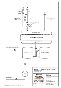 1. Baffled tanks
2. Straight Leg Tanks
3. Flow Through (or “Surge” Tanks)Surge tank designs essentially are tanks serving as a receiver for thermal fluid from the user with the main circulating pump drawing thermal fluid from the bottom of the tank for return to the heater. This design offers no oxidation protection and in fact increases oxidation due to the aeration of the thermal fluid in the tank itself. This is a poor design for extended thermal fluid use but does provide excellent thermal system venting capabilities during startup and extended operation.The baffled tank has three chambers or baffles. As the thermal fluid is heated, expansion of the fluid occurs from the first chamber into the second, and then into the main tank. In a properly sized expansion tank, when a thermal system is properly filled with cold thermal fluid there will be a significant level of fluid in the main baffle. With this type of design, thermal fluid in the main baffle rarely, if ever, co-mingles with hot fluid in the primary thermal system heat transfer loop because of inherent system fluid pressures. The fluid in the main baffle is significantly cooler than in the other baffles, forming a thermal blanket over the fluid in the primary thermal system heat transfer loop materially decreasing degradation of the thermal fluid due to oxidation.
As a general rule, in liquid phase thermal systems the expansion tank volumes should be approximately 26% – 30% of the total estimated volume of thermal fluid in the thermal system. The properly sized expansion tank should be approximately 1/4 full at startup temperatures and 3/4 full at operating temperatures.As the thermal system is brought up to operating temperature, the straight leg design allows the expanded thermal fluid to enter directly into the bottom of the main expansion tank by means of a small diameter pipe bypassing the flow-through valves under the expansion tank on the pump suction side of the tank Since the expansion tank is located at the highest point of the thermal system, the bulk of the thermal fluid will flow directly to the heater. Similar inherent fluid pressures as seen in the baffled tank keep thermal fluid in the expansion tank from co-mingling freely with fluid in the primary thermal system heat transfer loop. This type of design does not offer the same oxidation protection as the baffled design and, depending on system temperatures, an inert gas blanket may be required. Excellent thermal system venting may be accomplished by configuring the main line tank bypass valving to run through the expansion tank.
1. Baffled tanks
2. Straight Leg Tanks
3. Flow Through (or “Surge” Tanks)Surge tank designs essentially are tanks serving as a receiver for thermal fluid from the user with the main circulating pump drawing thermal fluid from the bottom of the tank for return to the heater. This design offers no oxidation protection and in fact increases oxidation due to the aeration of the thermal fluid in the tank itself. This is a poor design for extended thermal fluid use but does provide excellent thermal system venting capabilities during startup and extended operation.The baffled tank has three chambers or baffles. As the thermal fluid is heated, expansion of the fluid occurs from the first chamber into the second, and then into the main tank. In a properly sized expansion tank, when a thermal system is properly filled with cold thermal fluid there will be a significant level of fluid in the main baffle. With this type of design, thermal fluid in the main baffle rarely, if ever, co-mingles with hot fluid in the primary thermal system heat transfer loop because of inherent system fluid pressures. The fluid in the main baffle is significantly cooler than in the other baffles, forming a thermal blanket over the fluid in the primary thermal system heat transfer loop materially decreasing degradation of the thermal fluid due to oxidation.
As a general rule, in liquid phase thermal systems the expansion tank volumes should be approximately 26% – 30% of the total estimated volume of thermal fluid in the thermal system. The properly sized expansion tank should be approximately 1/4 full at startup temperatures and 3/4 full at operating temperatures.As the thermal system is brought up to operating temperature, the straight leg design allows the expanded thermal fluid to enter directly into the bottom of the main expansion tank by means of a small diameter pipe bypassing the flow-through valves under the expansion tank on the pump suction side of the tank Since the expansion tank is located at the highest point of the thermal system, the bulk of the thermal fluid will flow directly to the heater. Similar inherent fluid pressures as seen in the baffled tank keep thermal fluid in the expansion tank from co-mingling freely with fluid in the primary thermal system heat transfer loop. This type of design does not offer the same oxidation protection as the baffled design and, depending on system temperatures, an inert gas blanket may be required. Excellent thermal system venting may be accomplished by configuring the main line tank bypass valving to run through the expansion tank.
Selecting a Pump for Your Heat Transfer System
By Gerard Bernaldo, Fluid Specialist Engineer
When selecting the proper pump for heat transfer systems, there are several factors to consider. The pump must accommodate for a system’s temperature, pressure, and fluid properties. If a pump is chosen incorrectly, it can result in inefficient system performance or even lead to pump malfunction, such as pump seal damage and leakage. Choosing the best pump for your application can be a daunting task, but knowing which types of pumps are suitable for certain situations can make the decision a lot easier.
There are two main types of pumps used in high heat transfer systems. Positive displacement pumps displace liquid by creating a cavity between the moving components, into which fluid fills. The fluid is then forced out when the mechanism closes those gaps. Please note this article only refers to rotary positive displacement pumps. Reciprocating positive displacement pumps are not designed for use with heat transfer fluid. Centrifugal pumps use a rotating impeller, motor or turbine driven, to create kinetic energy, which increases the static fluid pressure. Fluid enters the pump through the impeller along its rotating axis, and discharges radially to the outlet. Magnetic driven pumps are a unique sealless option, in which integrated magnets drive each other to turn a canister-enclosed shaft. Magnetic pumps are similar to centrifugal pumps in that the driving magnets are also motor driven. Each type of pump has its advantages and disadvantages, which are discussed in further detail.
One of the most important system design points to address is fluid viscosity. If this is properly considered, you can eliminate which pumps would not perform proficiently. Keep in mind that heat transfer fluid viscosity increases considerably at low temperatures. See table 1.
A heat transfer fluid’s operating range is the temperature range between the pumpability point and the recommended maximum fluid operating temperature. The pumpability point is defined as the temperature where a fluid’s viscosity reaches 2000 centipoises. At this point, the fluid becomes too viscous for centrifugal pumps to maintain fluid flow. It is important to note that the pumpability of the fluid is usually only a factor at startup. Although heat transfer fluids technically can be used at temperatures close to their pumpability points, many fluids (especially petroleum-based fluids) lose much of their heat transfer efficiency if used close to their pumpability point.
Centrifugal pumps operate best with low viscosity liquids, typically ranging up to 550 cP. In this range, centrifugal pumps are capable of handling essentially most heat transfer fluids on the market. However, since they operate at motor speed, pump efficiency and flow rate drop significantly as viscosity increases. This is due to increased frictional losses within the pump’s mechanism. Positive displacement pumps excel in this category. They can effectively operate in a wide range of viscosities, and even more exceptionally at high viscosities (some can operate up to 1,000,000 cP!) Highly viscous fluid fills up clearances within the pump cavities, consequently improving pump operation.
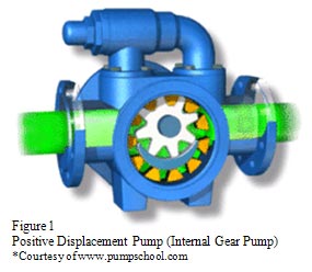 Conversely, positive displacement pumps, such as the internal gear pump shown in Figure 1, cannot dispel fluid in great quantities. Instead, positive displacement pumps are capable of delivering a constant, pulse-free flow through the system, independent of variations in system pressure. Centrifugal pumps can operate proficiently under certain pressures, but their efficiency significantly drops as system pressure increases. Most heat transfer systems are designed for operation under 50 psi, in which case, both centrifugal and positive displacement pumps can be used. Centrifugal pumps can be sized for head pressures up to 55 psi (125 ft.)The next considerable aspect of pump selection is system capacity. The main advantage of centrifugal pumps is their ability to transfer large volumes of liquid (up to 120,000 gallons per minute.) Processes can even be designed with several centrifugal pumps in parallel to maximize fluid discharge.
Net Positive Suction Head, more commonly referred to as “system pressure,” is the sum of several factors determined by system design. The NPSH is determined by the following:
Conversely, positive displacement pumps, such as the internal gear pump shown in Figure 1, cannot dispel fluid in great quantities. Instead, positive displacement pumps are capable of delivering a constant, pulse-free flow through the system, independent of variations in system pressure. Centrifugal pumps can operate proficiently under certain pressures, but their efficiency significantly drops as system pressure increases. Most heat transfer systems are designed for operation under 50 psi, in which case, both centrifugal and positive displacement pumps can be used. Centrifugal pumps can be sized for head pressures up to 55 psi (125 ft.)The next considerable aspect of pump selection is system capacity. The main advantage of centrifugal pumps is their ability to transfer large volumes of liquid (up to 120,000 gallons per minute.) Processes can even be designed with several centrifugal pumps in parallel to maximize fluid discharge.
Net Positive Suction Head, more commonly referred to as “system pressure,” is the sum of several factors determined by system design. The NPSH is determined by the following:
After calculating NPSH available (NPSHA), a pump with the appropriate NPSH required (NPSHR) can be chosen. NPSHA must be greater than NPSHR to avoid pump cavitation during system operation. Cavitation occurs when a fluid’s liquid pressure drops below its vapor pressure, causing the liquid to boil. Vapor bubbles produce pump noise and vibration, pitting damage to the impeller, and a sharp reduction in pump head and discharge. If a pump with a proper NPSH rating is selected, cavitation can be prevented.
Once the correct pump is selected for an application, several shaft sealing options can be considered. One of the earliest forms of shaft seals is packing, which is made up of braided or formed rings compressed in the stuffing box of a pump. This type of sealing requires lubrication, either by the circulating system fluid, or externally. The main advantage of packing is that it rarely fails catastrophically. It is most effectively used in applications with thick, non-abrasive liquids. Elastomeric lip seals are also ideal for similar applications. While traditionally used for low pressure applications, technological advancements in newer seals allow for operation in high pressure systems (150-psi or greater) as well. The drawback to using a lip seal is the possibility of catastrophic failure, which could trigger more serious pump problems. Mechanical seals share this same disadvantage.
Basically, mechanical seals consist of faces sliding against one another to form a seal. Similar to seal packing, mechanical seal faces are typically lubricated by the circulating fluid or other external methods. The most prominent benefit of mechanical seals is the wide variety of designs to accommodate a broad range of liquids, viscosities, pressures, and temperatures. Moreover, they are designed to be easily replaced or repaired. As mentioned earlier in this article, sealless magnetic driven pumps are becoming a popular option for hard-to-contain liquid applications. Although sealless pumps are a more costly alternative, they offer exceptional dependability and absolutely no leakage.
In conclusion, there are several factors to consider when deciding which pump is most ideal for your heat transfer application. Although there is an extensive variety of pump options to choose from, knowing the capabilities of your system can help you narrow down the field.
|
||||||||||||||||||||||||
Conversely, positive displacement pumps, such as the internal gear pump shown in Figure 1, cannot dispel fluid in great quantities. Instead, positive displacement pumps are capable of delivering a constant, pulse-free flow through the system, independent of variations in system pressure. Centrifugal pumps can operate proficiently under certain pressures, but their efficiency significantly drops as system pressure increases. Most heat transfer systems are designed for operation under 50 psi, in which case, both centrifugal and positive displacement pumps can be used. Centrifugal pumps can be sized for head pressures up to 55 psi (125 ft.)The next considerable aspect of pump selection is system capacity. The main advantage of centrifugal pumps is their ability to transfer large volumes of liquid (up to 120,000 gallons per minute.) Processes can even be designed with several centrifugal pumps in parallel to maximize fluid discharge.
Net Positive Suction Head, more commonly referred to as “system pressure,” is the sum of several factors determined by system design. The NPSH is determined by the following:
|
*NPSH = HA ± HZ – HF + HV – HVP |
||
| Term | Definition | Notes |
| HA | The absolute pressure on the surface of the liquid in the supply tank | Typically atmospheric pressure (vented supply tank), but can be different for closed tanks. Don’t forget that altitude affects atmospheric pressure (HA in Denver, CO will be lower than in Miami, FL). Always positive (may be low, but even vacuum vessels are at a positive absolute pressure) |
| HZ | The vertical distance between the surface of the liquid in the supply tank and the centerline of the pump | Can be positive when liquid level is above the centerline of the pump (called static head) Can be negative when liquid level is below the centerline of the pump (called suction lift.) Always be sure to use the lowest liquid level allowed in the tank. |
| HF | Friction losses in the suction piping | Piping and fittings act as a restriction, working against liquid as it flows towards the pump inlet. |
| HV | Velocity head at the pump suction port | Often not included as it’s normally quite small. |
| HVP | Absolute vapor pressure of the liquid at the pumping temperature | Must be subtracted in the end to make sure that the inlet pressure stays above the vapor pressure. Remember, as temperature goes up, so does the vapor pressure. |
| *Table and equation courtesy of www.pumpschool.com | ||
| External References www.lightmypump.com www.pumpschool.com www.pump-zone.com Recommended Pump Manufacturers/Distributors Dean Pump 6040 Guion Road Indianapolis, IN 46254 Phone: 317-293-2930 Fax: 317-297-7028 Dickow Pump Company, Inc. 1738 Sands Place Marietta, GA 30067 Toll Free: 877-952-7903 Phone: 770-952-7903 Fax: 770-933-8846 Industrial Products Goulds Pumps, ITT Corporation 240 Fall St. Seneca Falls, NY 13148 Phone: 315-568-2811 Fax: 315-568-2418 Travaini Pumps USA 200 Newsome Drive Yorktown, VA 23692 Phone: 757-988-3930 Fax: 757-988-3975 Viking Pump, Inc. A Unit of IDEX Corporation 406 State Street, P.O. Box 8 Cedar Falls, IA 50613-0008 Phone: 319-266-1741 Fax: 319-273-8157 |
|
Xceltherm CLX System Cleaner
PERFORMANCE DATA ANALYSIS
By Doug McKinney
The cleaning efficiency of XCELTHERM® CLX SYSTEM CLEANER is determined by the “Firing Residue Removal” test developed by the US Army. The Firing Residue Removal test quantifies the percentage of burned gunpowder that is removed from a surface by a weapons cleaning fluid. The standard operating procedure for Firing Residue Removal is described in the US Army specifications for MIL-PRF-372rifle bore cleaners (RBC), and MIL-PRF-63460 cleaner, preservative and lubricant fluids (CLP).
For this study, a 10% by volume XCELTHERM® CLX mixture in XCELTHERM® HFF was measured. The mixture removed 79% firing residue. In comparison, new XCELTHERM® HFF has a typical residue removal of 30%.
Firing residue removal efficiency is measured by the removal of burned WC 844 rifle propellant in a porcelain evaporating dish (Figure 1). The burned propellant forms a hard carbon layer (“scale”) that adheres to the porcelain dish (Figure 2). The sample is poured into the burned dish, and it is baked in a convection oven at 54°C (129°F) for 45 minutes. When the dish is removed from the oven it is swabbed with a surgical cotton gauze. No downward pressure is applied during the swabbing (Figure 3). Residue removal value is the percent difference determined by the mass of the burned rifle propellant before and after cleaning the dish.
How to Start Up and Shut Down Heat Transfer Systems
From Process Heating Magazine October 2015 Edition
Follow these guidelines to ensure that fluids and systems are protected.
October 16, 2015 Alison Davis, Radco Industries Inc. and Jed Seybold, Radco Industries Inc. Heat transfer fluids are vital to many processes worldwide. To ensure their ongoing, safe operation, it is important to protect the fluid not only during regular operation but also during system startup and shutdown. Here are some guidelines to ensure a smooth startup and shutdown of your heat transfer system.
Characterization of Fluid Flow in Industrial Processes
The two primary characterizations of fluid flow in a pipe are laminar flow and turbulent flow. Laminar flow is described as a smooth, layered flow in which the quickest flow happens at the center of the pipe. Turbulent flow is choppy and tumultuous with no specific pattern. The point at which fluid flow transitions from laminar to turbulent flow is defined by the Reynolds number, a dimensionless number characterized by the length of pipe through which the fluid is traveling, and the fluid’s density, viscosity and velocity. In a heat transfer fluid heating system, when the pump and heater are turned on, the velocity of the fluid increases and the viscosity decreases. The velocity and viscosity changes make the Reynolds number increase. Once the Reynolds number is greater than 2000, the fluid flow is considered turbulent. The transition from laminar flow to turbulent flow is important during startup due to the layered nature of laminar flow. As noted, during laminar flow, the fluid at the center of the pipe flows most quickly. The fluid at the outside of the flow forms a stagnant layer along the pipe wall where the heat transfer happens. If heated too quickly, this layer will inhibit heat transfer and the fluid will exceed its bulk film temperature, causing thermal cracking and carbon and sludge buildup. Turbulent flow of the heat transfer fluid allows for superior heat transfer and maximum thermal efficiency along the wall of the pipe. For this reason, the most critical thing to remember during startup of a heat transfer system is to begin circulation of the fluid before raising the system temperature. Quick disconnect valves speed the process of loading and unloading.
Startup of Heat Transfer Systems for Industrial Processes
Many steps are required to properly start up a heat transfer system. Whether the system is brand new or has been previously used, all systems should be flushed before startup to remove any debris or residue trapped in the piping. After flushing, the heat transfer fluid must be charged into the system. Finally, the system should be started slowly and carefully to avoid damage to the heat transfer fluid. Here is a closer look at each of these key steps. Flushing the System. To complete a flush of a heat transfer system, the system should be filled to 80 percent of its total volume with flushing fluid, according to the filling instructions (see below), and run for eight hours at 400°F (204°C). It is important to use the correct flushing fluid for your system, whether it is a hot oil system or a synthetic heat transfer system. Your heat transfer fluid supplier can help you choose the correct flushing fluid. Drain the flushing fluid before proceeding to the next step. Filling the System. The system should be charged with heat transfer fluids through low points in the system. One main objective in starting up a heat transfer system should be to remove any additional moisture or other light-end fluids trapped in the system. (Light-end fluids are contaminants with a boiling point lower than that of the heat transfer fluid.) To do this, the fluid should be run through the expansion tank during startup. Any moisture or light-ends escaping may cause a brief increase in system pressure or puffs of vapor leaving the expansion tank vent. The expansion drum should be filled and drained continuously to aid in venting nitrogen and to fill the system. Once the system has been filled, nitrogen and any additional moisture or light-ends can be vented through bleeder valves at high points of the system. After the system is completely filled and nitrogen has been vented, the circulation pump can be turned on. Starting the System. The pump always should be started before the heater is turned on to ensure that the fluid is circulating and reaches turbulent flow before being heated. Once the fluid is circulating, the following steps should be taken to bring the system up to the desired operating temperature:- 1. Increase the heat at a rate of 1°F (~0.5°C) per minute or less until it reaches 200°F (93°C). Run one cycle.
- 2. Increase the heat at a rate of 1°F per minute or less until it reaches 230°F (110°C). Run one cycle.
- 3. Increase the heat at a rate of 1°F per minute or less until it reaches 260°F (127°C). Run one cycle.
- 4. Increase the heat at a rate of 1°F per minute or less until it reaches 300°F (149°C). Run one cycle. Bypass the expansion tank if the system has been running normally.
- 5. Increase the heat at a rate of 50°F (~25°C) per minute or less until it reaches the desired operating temperature. Run one cycle under observation.

Shutdown of Heat Transfer Systems
As previously mentioned, it is critical that the heat transfer fluid be circulating when the system is operating at high temperatures. Therefore, during shutdown of a heat transfer system, the heat should be turned down before the pump is shut off. (In other words, the procedure follows the opposite order in which the system is started.) The fluid should circulate until the system temperature drops below 200°F (93°C), and the residual heat has been removed from the system. At this point, the system pump can be shut off.
Should Your System Use Synthetic or “Hot Fluid” Thermal Fluid?
By: Michael R. Damiani Radco Industries, LLC
Published in the October 1998 issue of Process Heating magazine
High temperature heat transfer fluids are used in process applications where their optimum bulk fluid operating temperatures of 300°F to 750°F are safer and more efficient than steam, electrical, or direct fire heating methods. Selecting the proper heat transfer fluid for a new system while in the design phase or for possible process fluid improvements during an upcoming retrofit will assure sufficient and uniform BTU delivery (or removal). The properly selected heat transfer fluid will also minimize potential production loss and downtime due to required design changes, mechanical problems, or fluid failure. The process of selecting the optimum heat transfer fluid should begin once the energy transfer required by the process and the planned/actual service ratings of the mechanical components of the heat transfer system have been calculated and thoroughly researched. Since there are a number companies specializing in heat transfer fluids and a wide range of fluid products available, the knowledge of this key element of the system’s operating requirements can help to create a set of criteria that can be used to compare various fluids and allow rapid elimination of fluids that are not best suited for the application. However, before comparing and contrasting various individual fluids, much time and effort in the selection process can be saved by comparing and contrasting the various chemistries of the fluids. Once a fluid chemistry is selected that best meets the performance properties and other criteria required by the application, the resultant list of potential fluids becomes significantly more manageable for more detailed apples-to-apples comparisons.
Fluid Chemistry. High temperature heat transfer fluids can be categorized by chemical structure into three primary groups:
1. Synthetics
2. Hot Oils
3. “Others” including silicones
The synthetics, also referred to as “aromatics”, consist of benzene-based structures and include the diphenyl oxide/biphenyl fluids, the diphenylethanes, dibenzyltoluenes, and terphenyls. Depending on the specific product, the overall bulk fluid temperature operating range of the synthetics is from -70°F to 750°F.
The hot oils are petroleum-based and most consist of paraffinic and/or napthenic hydrocarbons. The overall bulk fluid temperature operating range of the petroleum-based fluids is from -10°F to 600°F, with the high-grade hydrogenated white oils strongly recommended for applications requiring bulk fluid temperatures in the 575°F to 600°F range.
Silicone-based fluids, and to a greater extent hybrid glycol fluids, are used primarily in specialized applications requiring process/product compatibility should a heat exchanger leak occur. This group’s performance and cost factor disadvantages in the comparative temperature ranges of the synthetics and hot oils make silicone-based and other specialty fluids unlikely choices for most process applications.
Fluids and System Types. Hot oils and synthetics are used in a multitude of heat processing applications. The type of system design used in the process is a major consideration on the choice of a specific fluid chemistry. Processes utilizing heat transfer fluids can be categorized into three system types:
1. Non-pressurized liquid phase systems.
2. Pressurized liquid phase systems.
3. Pressurized pumped or natural circulation vapor-phase systems.
Non-pressurized liquid phase systems are generally the simplest to design and operate. Both hot oils and synthetics can be used equally well in this type of system as long as the operating temperature of the heat transfer fluid is below its boiling range. Major components in these systems consist of the heater, heat exchanger, vented expansion tank, and circulating pump. The expansion tank need not have inert gas applied in these types of systems in order to keep positive pressure on the circulating pump. To reduce the probability of fluid oxidation, a baffled expansion tank design is preferred to assure the fluid is below 350°F at the fluid/atmosphere interface.
Pressurized liquid phase systems using both hot oils and synthetics are similar in design to non-pressurized systems except that inert gas is applied through the expansion tank when the required operating temperature of the heat transfer fluid is above its boiling range. The pressurized inert gas (nitrogen) is used to maintain the heat transfer fluid as a liquid. The inert gas also acts as a buffer in the expansion tank between the hot fluid surface and the atmosphere, eliminating fluid oxidation. With the exception of the multi-phase fluids like the diphenyl oxide/biphenyl-type, most of the liquid phase synthetics and all of the hot oils do not require inert gas pressurization to maintain the liquid phase at their top-end recommended operating temperatures.
Pressurized vapor-phase systems utilize only a handful of synthetic fluids, most notably the diphenyl oxide/biphenyl-type. A simple vapor phase system can be designed using hydrostatic pressure to gravity return the condensate from the user to the vaporizer, eliminating the need for a condensate pump. More complex systems require a flash tank, condensate return tank, and a condensate return pump. The disadvantage of the added capital equipment cost and the complexity of vapor phase systems is offset by the increased BTUs delivered per pound of vapor versus liquid, and increased temperature control at the user- important in heat sensitive processes.
Criteria For Selecting The Best Fluid Chemistry. If a existing system or a system on the design board is a vapor phase system and requires a high temperature fluid, the fluid options are extremely limited. Only a handful of high temperature vapor phase synthetic fluids are available from different heat transfer fluid manufacturers. Hot oils cannot be used in the vapor phase. Therefore, non-pressurized or pressurized liquid phase systems allow the greatest variance in potential end-use fluids, both synthetic and petroleum-based. Especially in existing systems, the wide range of new liquid phase fluid technology available offers possibilities of increased system performance and energy savings with a minimum of downtime and cost. Whether researching a potential fluid upgrade in an existing system or specifying the proper fluid type and fluid into a new design, the following basic criteria should be considered:
Thermal Stability. Thermal stability is simply defined as the inherent ability of a heat transfer fluid to withstand molecular cracking from heat stress. Relative thermal stability testing of heat transfer fluids measures a particular fluid’s molecular bond strength at a specific temperature versus another particular heat transfer fluid at the same temperature and under identical testing conditions. ‘Relative’ is the key word- since the tests are run under ideal laboratory conditions and do not factor in real-world fluid stresses such as mechanical malfunctions, design flaws, oxidation, etc., the data generated is useful for comparative purposes only. Accurate predictions of fluid life in actual processing applications should not be implied from thermal stability data.
A fluid’s thermal stability is the primary factor in determining its maximum bulk fluid operating temperature. This is the maximum temperature the fluid manufacturer recommends the fluid can be used and still maintain an acceptable level of thermal stability. Since fluid degradation rates are closely tied to temperature, continuous use above the manufacturer’s recommend maximum bulk fluid operating temperature will increase degradation rates exponentially. Potential system problems caused by excessive degradation and the subsequent formation of degradation by-products include increased coking and fouling, mechanical difficulties, and decreased heat transfer efficiency. Therefore, in selecting a fluid chemistry, the first step in the selection process is to determine the maximum bulk operating temperature required by the process. Most hot oils have a recommended maximum bulk fluid temperature of 550°F – 600°F, while the aromatics have recommended maximum bulk fluid temperatures between 600°F- 750°F, depending on the fluid. Since the molecular structures of the aromatics are significantly more thermally stable than the hot oils above 600°F, in applications above this temperature aromatic-based heat transfer fluids are strongly recommended. Process applications requiring bulk fluid temperatures from 300°F to 600°F can specify either synthetic or petroleum-based fluids. Within this temperature range relative thermal stability data supplied from fluid manufacturers is available to compare individual fluids at specific temperatures.
Heat Transfer Efficiency. Heat transfer efficiency comparisons between heat transfer fluids are made using heat transfer coefficients. At a specific temperature, a fluid’s overall heat transfer coefficient can be calculated using its density, viscosity, thermal conductivity and specific heat at a determined flow velocity and pipe diameter. The resultant heat transfer coefficients may be then evaluated and compared. At a given temperature, the heat transfer coefficients of the fluid types may differ as much as 30%. Depending on the thermal resistance factors of the other components in the system, a fluid with a substantial heat transfer coefficient advantage may allow a reduction in sizing of system equipment. Replacing existing heat transfer fluid with a more efficient heat fluid may significantly increase production output and/or reduce energy costs. Most of the aromatic-based fluids have a significant advantage in heat transfer efficiency over hot oils from 300°F to 500°F. Above this temperature range (up to 600°F) petroleum fluids narrow the difference somewhat with a select number of highly refined paraffinic/napthenic white oils having a slight efficiency advantage over the mid-range aromatics.
Keep in mind the heat transfer coefficient is calculated using virgin fluid properties. Fluid that has been in service for an extended period of time and has undergone thermal degradation may have a significantly lower coefficient due to fluid viscosity changes and the presence of less efficient fluid degradation by-products. Therefore, a fluid’s thermal stability plays an important role in maintaining its thermal efficiency over time.
Pumpability Point. Pumpability point, not freeze point, is the true low-end temperature a heat transfer fluid can operate in heat process applications. The pumpability point is defined as the temperature at which the viscosity of the fluid reaches a point (typically 2000 cP) where centrifugal pumps can no longer circulate the fluid. Although most high temperature process applications run at bulk temperatures well above hot oil and aromatic pumpability points, system designs that might encounter cold weather during emergency shutdowns, maintenance shutdowns, or operate a batch process in a cold climate, should take into account fluid pumpability points. Generally, most of the hot oils offer adequate start-up protection down to the 0°F to +25°F range. The mid-temperature aromatics (with 650°F maximum bulk temperatures) offer protection down to -70°F to -20°F, while the top-end temperature aromatics (with 700°F- 750°F maximum bulk temperatures) are at +40°F to +60°F. Processes using a fluid that potentially may have start-up problems in cold weather will need to be heat traced.
Fluid Serviceability. Fluid replacement, reprocessing, or filtration may be required from time to time due to unexpected temperature excursions, system upsets, or contamination. Because of the relatively low cost of petroleum-based fluids, very few suppliers offer reprocessing services for hot oils or a credit program for the off-spec material that can be applied toward the cost of a new charge. Most synthetics are composed of a limited number of aromatic components and have a narrow boiling range, allowing easy identification of degradation by-products and/or contaminants. Reprocessing synthetics using fractional distillation is an economical alternative to disposal and replacement; hence, most synthetic fluid suppliers offer this service at a nominal cost. Some synthetic fluid suppliers also offer credit for off-spec material- this credit is then applied to the purchase cost of the replacement charge. These programs eliminate fluid turnaround and reprocessing time, since the new fluid can be charged in immediately after the off-spec fluid has been drained. This is especially useful if the system downtime is unscheduled or a short maintenance period has been planned.
Filtration versus reprocessing or fluid replacement is a cost effective method of removing carbon and coke suspended in the heat transfer fluid. Most fluid suppliers recommend slipstream filter loops permanently installed and closely maintained on both hot oil and synthetic systems. Fluid filtering companies with portable units are also available to setup on-site and remove carbon from the fluid while the unit is still operating. Almost all suppliers of both synthetic and petroleum-based heat transfer fluids offer analytical testing of fluid condition at no-charge. This important service monitors fluid condition over time and gives an early warning should action need to be taken to replace, reprocess, or filter the fluid.
Environmental. Comparing environmental and personnel guidelines is just as important when selecting a heat transfer fluid chemistry as comparing fluid performance. In general, all heat transfer fluids do not present an appreciable health hazard when used in accordance with acceptable manufacturing practices. However, the petroleum-based fluids offer substantial advantages in ease of handling, reprocessing, shipping and disposal as compared to the synthetics. For one, most hot oils do not have a reportable spill quantity, and in the cases of the white mineral oils, meet the FDA and USDA criteria for ‘incidental food contact’. Also, the petroleum-based fluids do not form hazardous degradation by-products, therefore most spent hot oils can be sent to a local oil/lube recycler for disposal. Finally, the hot oils tend to warrant no special handling precautions, are not DOT regulated, and require no special storage requirements. From a personnel standpoint, the hot oils are extremely user-friendly. Most have a non-discernible odor and are non-toxic both in contact with skin and ingestion.
Because of the aromatic-based chemistry of most of the synthetics, some fluids can form hazardous degradation by-products that require special permits, handling and shipping precautions. Some synthetics and their vapors may cause skin and eye irritation after prolonged exposure, and emit pungent odors. In some cases, spills of synthetic fluids require reporting under the Superfund Amendments and Re-authorization Act. Since there is a wide range of chemistries available within the aromatic group, not all fluids have similar properties and environmental/personnel concerns. Regulations and precautions vary from fluid to fluid.
Cost. As a general rule, the higher the bulk fluid temperature a fluid is rated, the higher the cost of the fluid. The synthetics rated for use above 650°F are two to three times more expensive than the average hot oil rated to 600°F, while aromatics rated from 600°F to 650°F are one and a half to two times the cost of the average hot oil.
Which Chemistry Is The Best? Chances are one fluid chemistry is not superior to the other in every criteria required by a new process or retrofit. Both fluid chemistries have advantages- the aromatics offer superior heat transfer efficiency and stability at elevated temperatures coupled with serviceability and adequate pumpability, while the hot oils have a significant cost and environmental/personnel advantage. Identification of the primary criteria required by a new process or the main improvement goal desired in a retrofit will prioritize the criteria by importance. Is the goal more output and/or shorter production runs? A personnel/environmentally friendly system? Longer period of time between shutdown and fluid replacement? By first selecting the fluid chemistry that best solves the big picture, comparisons of individual fluids within the group should solve the little ones.
Specifying Heat Transfer Fluid For Food Processing Applications
By Pete Frentzos, Radco Industries Inc.
Defining “food grade” and a new set of regulations from NSF International make it easier for process engineers in food manufacturing to choose a heat transfer fluid.
Until recently, the term “food grade” has been used loosely to describe heat transfer fluids that are suitable for food processing applications. It has not been a term that specifically describes heat transfer fluids in their stated use but was an inference made from other regulations. There was an enthusiastic salesperson who would take a drink of fluid to prove to his customers eth validity of this inference. While possibly valid, it’s not recommended.The Food and Drug Administration (FDA), Washington, under a wide range of regulations, defines the food additive status of a number of products, but not specifically heat transfer fluid. One can refer to Title 21 of the Code of Federal Regulations (CFR) online (see sidebar “See for Yourself”). These chemicals are listed under part 170 subsections. It covers additives designed for indirect food additives, secondary food additives, indirect food additives of a specific chemical family, and so on. Because the same chemicals can be part of a heat transfer fluid product line, this became one of the standards called “food grade.”
 Founded in 1944 as the National Sanitation Foundation, NSF International, Ann Arbor, Mich., is known for the development of standards, product testing and certification services in the areas of public health, safety and protection of the environment. NSF became involved when the USDA decided that it would no longer maintain its list. At first, NSF acted as record keeper to ensure the list was available for review. Now, the organization has taken an active role to refine the list. NSF created the Non-Foods Compound Group to define the use of heat transfer fluid, fluid additives and lubricants, as well as other materials, separately for their specific applications.Likewise, until recently, the United States Department of Agriculture (USDA), Washington, had its own regulations, which included mineral oils used as machinery lubricants and release agents to prevent meat from sticking to grills. The reference, H1 status, was used to indicate that the oil was acceptable for use in meat and poultry establishments and could have incidental food or feed contact. Again, these same mineral oils can be part or all of what is used as a “hot oil” for heat transfer.
Kenji Yano, program manager of the nonfood compounds registration program explains, “The term ‘food-grade’ is not used. …Instead ‘incidental contact’ (HT1) is used as opposed to ‘nonfood contact’ (HT2) compounds.” NSF keeps this list online, on CD and in its “White Book,” which is published annually.
Founded in 1944 as the National Sanitation Foundation, NSF International, Ann Arbor, Mich., is known for the development of standards, product testing and certification services in the areas of public health, safety and protection of the environment. NSF became involved when the USDA decided that it would no longer maintain its list. At first, NSF acted as record keeper to ensure the list was available for review. Now, the organization has taken an active role to refine the list. NSF created the Non-Foods Compound Group to define the use of heat transfer fluid, fluid additives and lubricants, as well as other materials, separately for their specific applications.Likewise, until recently, the United States Department of Agriculture (USDA), Washington, had its own regulations, which included mineral oils used as machinery lubricants and release agents to prevent meat from sticking to grills. The reference, H1 status, was used to indicate that the oil was acceptable for use in meat and poultry establishments and could have incidental food or feed contact. Again, these same mineral oils can be part or all of what is used as a “hot oil” for heat transfer.
Kenji Yano, program manager of the nonfood compounds registration program explains, “The term ‘food-grade’ is not used. …Instead ‘incidental contact’ (HT1) is used as opposed to ‘nonfood contact’ (HT2) compounds.” NSF keeps this list online, on CD and in its “White Book,” which is published annually.
Qualifying Fluids and Specific Uses
When to use which type of heat transfer fluid depends on the requirements of the application.
Whether you choose FDA or NSF as your current guide, there are many fluids from which to choose. As an example, within the following chemistries are select fluids that are safe for “incidental food contact” — brine, potassium formate (KF), polyalphaolephin (PAO) and highly refined, severely hydrogenated paraffinic white oils. Both PAO and white oil chemistries are heat transfer fluids sometimes referred to as “hot oils.” When to use which one depends on the requirements of the application; each has its own advantages and temperature ratings (table 1). When HT1 must be specified is easy to understand. If there is any chance of incidental food contact, it should be a requirement, even if not regulated, as a matter of good manufacturing practice. It is good economics, too. For example, a packaging line heats adhesive with heat transfer fluid. The adhesive is used to seal frozen food packaging. If a leak occurs in the heat exchanger, it could go undetected for a long time, and any premium paid for “incidental food contact (HT1)” fluid wouldn’t seem like much compared to a hundred thousand units of contaminated packages. There also is the matter of storage and overall production standards. The heat transfer fluid used should complement the environment where it is required. When the temperature requirement of the application exceeds 600oF (316oC) or surface temperatures on the heat exchange surface exceeds 650oF (343oC), the type of heat transfer fluid rated for incidental food contact should not be specified. At this point, the white oils, the highest temperature rated product of the group, do not have the thermal stability required for a long life. (There is some debate on this exact temperature, but 600oF bulk operating temperature is a good conservative number to work with.) In this case, aromatic/synthetic fluids or other high temperature fluids are the only choice.Beyond Food Use
Not every application needs to be in food processing to use HT1 fluids. A good example is the die-cast industry. The molds are heated, cooled or held at steady temperatures using heat transfer fluid. When the molds are opened or changed, some heat transfer fluid typically leaks from the inner chamber. The leaking fluid is captured for disposal, but this involves employee exposure to the fluid. HT1 fluids made from white oils are easy to handle because they are nontoxic and nonirritating to the skin. The lack of odor also results in fewer employee complaints. Due to the efforts by NSF International, process engineers, specifying engineers, maintenance engineers and technicians now can take advantage of a simple and straightforward guide for the type of fluid they want. There is no need to rely on a sales pitch or to sort through the voluminous FDA regulations and guess if a fluid really qualifies.Sidebar: Heat Transfer Fluids and Kosher Foods
Another specifying consideration in food processing is the need for kosher heat transfer fluid in applications that manufacture kosher products or products to be used in kosher foods. Even though heat transfer fluid is not put into the food directly, it must be kosher under the kosher laws that refer to heating a product through a common wall (in this case, a heat exchanger). Rabbi Sholem Fishbane of the Chicago Rabbinical Council (CRC), a kosher overseer agency, explains that this is an important requirement. Kosher laws state that this type of heating causes a mixture of flavors. Under kosher law the “spiritual flavor” will go through the metal and affect the liquid on the other side. If the kosher product is heated by a fluid that is not kosher, explains Rabbi Fishbane, this spiritual flavor will contaminate the kosher product. The concept of the mixing of flavors can lead to some interesting engineering issues. If a plant is broiling kosher chickens with a heat transfer fluid system and using the same fluid to process animal fats that contain pork in another part of the plant, under kosher law, the process has been contaminated. Likewise, in plants that produce both kosher and non-kosher or even dairy and pareve (non-dairy), engineers must carefully review details like returned condensate. The CRC makes frequent random inspections and is diligent in educating themselves to understand plant engineering, ensuring that kosher laws are not broken. This is of great service to the food processor by giving assistance to their process planning and provides a third-party certification of product quality. Rabbi Fishbane emphasizes that this requires a technical education supported through “constant attendance of seminars and lectures” and “not every agency’s approval is acknowledged by the CRC.” A specifying engineer needs to determine which agencies have the ability to make the types of inspections required for the specific application. Each heat transfer fluid manufacturer has the information on which agency they use. A note on kosher fluids is that the fluid also should be rated as kosher/pareve, which means it can be used for foods and additives intended for consumption on Passover and used all year. When the temperature requirement of the application exceeds 600oF (316oC) or surface temperatures on the heat exchange surface exceeds 650oF (343oC), a heat transfer fluid rated for incidental food contact should not be specified. What about kosher? Kosher law allows for a non-kosher fluid heating medium if that medium is made so foul that any contamination would make the food or additive that is heated inedible. By their nature, aromatic chemistries used for higher temperatures have a strong, pungent odor, especially when heated, and qualify readily for this exemption.Sidebar: See for Yourself
Visit these web sites for more information.- NSF International www.nsf.org
- Chicago Rabbinical Council www.crcweb.org
- United States Department of Agriculture www.usda.gov
- Food and Drug Administration www.fda.gov